

When the input signal is negative, the op-amp output swings negative and reverse biases D1. The circuit thus acts as a voltage follower to positive input signals. Negative feedback through D1 then forces the inverting input (and thus the circuit’s output) to accurately follow all positive input signals greater than a few microvolts. When positive input signals are applied to the circuit, the op-amp output also goes positive an input of only a few microvolts is enough to drive the op-amp output to the 600mV ‘knee’ voltage of D1, at which point, D1 becomes forward biased. The Figure 1 circuit is wired as a non-inverting amplifier with feedback applied via silicon diode D1, and with the circuit output taken from across load resistor R1. Figure 1 shows a simple half-wave rectifier of this type.įIGURE 1. This weakness can be overcome by wiring the diode into the feedback loop of an op-amp, in such a way that the effective knee voltage is reduced by a factor equal to the op-amp’s open-loop voltage gain the combination then acts as a near-perfect rectifier that can respond to signal inputs as low as a fraction of a millivolt. Simple diodes are poor rectifiers of low-level AC signals, and do not start to conduct until the applied voltage exceeds a certain ‘knee’ value silicon diodes have knee values of about 600mV, and thus give negligible rectification of signal voltages below this value. Also note that all 741-based circuits have a very limited frequency response, which can be greatly improved by using an alternative ‘wide-band’ op-amp type. When reading this episode, note that most practical circuits are shown designed around a standard 741, 3140 ,or LF351-type op-amp and operated from dual 9V supplies, but that these circuits will usually work (without modification) with most voltage-differencing op-amps, and from any DC supply within that op-amp’s operating range. This month’s concluding episode looks at practical ways of using such op-amps in various instrumentation and test-gear applications, including those of precision rectifiers, AC/DC converters, electronic analog meter drivers, and variable voltage-reference and DC power supply circuits.
#741 op amp series#
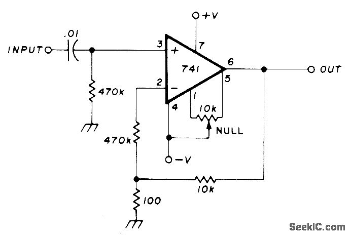
See a Intruder alarm circuit using IC 741 as a comparator.The opening episode of this four-part ‘op-amp’ series described the basic operating principles of conventional voltage-differencing op-amps (typified by the 741 type) and showed some basic circuit configurations in which they can be used. Pin 4&5-This was meant for positive and negative supply to the IC.ġ)INVERTING AMPLIFIER:In an inverting amplifier the input voltage enters through pin 2 and comes out of the pin 6 resulting in reversal of polarity.When the input voltage is positive output will be negative and if input negative out will be positive.Ģ)NON-INVERTING AMPLIFIER:In this type the input voltage enters the IC through pin 3 and leaves through pin 6.The polarity of the input voltage will obtain no change when coming out of the pin 6.ģ)COMPARATOR:This mode was something different from the above two modes and this was used in a circuit that compares two input voltages one voltage is reference voltage (Vref) and the other is called the input voltage (Vin).Whenever the Vin rises or falls below the Vref value the polarity of the output changes thus making it to work as a comparator. Pin6-This output of the IC was obtained from this pin. Pin3-This was input pin which does not change the polarity of the given input voltage and hence known as non-inverting input. Pin 2-This was input pin which was used to invert the input voltage value and hence known as Inverting input. Pins 1&5-These two pins are meant for adjusting the offset voltage in order to obtain better gain.Offset voltages occur due to manufacturing process and there will be small differences which combine to look like a single input voltage error so this pins was used to adjust the voltage value and eliminate the error. The IC 741 comprises of 8 pins as you can see in above pin diagram. This article was meant you to understand the basic working of op amp 741 and how it was implemented in circuits.The IC 741 was the most common Operational Amplifiers used since it was very cheap and provides high gain value.There are three main modes that this IC 741 was used they are


 0 kommentar(er)
